Electronic Nirvana

Beginner Circuit 3 - Buzzer - Tiva Launchpad TM4C123GXL (Without writing any code)

1/18/2014

0 Comments

 
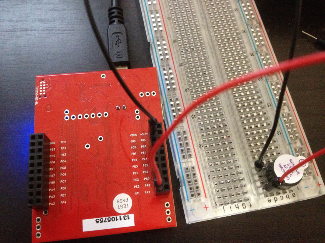
Continuing from my earlier simple circuits that make use of the preloaded RGB quickstart program on the Tiva TM4C123GXL launchpad, i made this simple circuit to see if i can hear any sound. Since the RGB quickstart application seem to be varying the input to the 3 different LED pins, i thought may be if i connect it to a piezo buzzer, i though i can hear some sound. Exactly that's what happened!!!  

Connections:
1. PF1 to Positvie (long pin) of the buzzer. (Red wire)
2. GND to Negative (short pin) of the buzzer. (Black wire)
Picture
Here is a video:
0 Comments

Beginner Circuit 2 Tiva Launchpad TM4C123GXL (Without writing any code)

1/18/2014

0 Comments

 
Continuing from my earlier circuit to connect external LEDs to the pre-loaded program, here I connected external push buttons to control the LEDS on Tiva. 

Connections are:
1. GND Pin to GND Rail on the Bread Board (Green wire in the picture)
2. One wire from GND rail to one side of the button (White). Do the same with the other button as well.
3. PF4 and  PF0 are the button input pins on Tiva. So Connect one wire from PF4 to other side of button 1 ( blue/black wire). Connect another wire from PF0 to the other side of Button 2.(red wire) 

You are good to go. Now if you press the buttons on the bread board, you should see the same functionality as the buttons on the Tiva Launchpad.
Picture
Remember that this circuit works only with the pre-loaded quick start RGB on the Tiva TM4C123GXL launchpad. This is just to do some experiments with the board while I wait for the Edx Embedded systems shape the world MOOC course to start. 
0 Comments

Beginner Circuit Tiva Launchpad TM4C123GXL (Without writing any code)

1/13/2014

1 Comment

 
I am sure this is something that most of us who have signed up for the Embedded Systems Shape the world course would be going through while waiting for the course to start on Jan 22. I have been anxious to get a first circuit built ever since I got the Tiva Launchpad for the edx course. Without writing any new code, and without frying the board i wanted to build some kind of circuit. So decided to use the launched QuickStart rgb application that came with the board as the base software and connect my external circuit to it.  

Here is what we know about the pre-loaded RGB Quick Start application from the instruction leaflet that came pre-loaded with the Tiva Launchpad:
  1. It controls the LED
  2. It uses the two buttons that are present on the board

From the LaunchPad Evaluation Kit Manual I see the following pin mapping used by the RGB Quick start application
Table 2-2. User Switches and RGB LED Signals
GPIO Pin Pin Function USB Device
PF4 GPIO SW1
PF0 GPIO SW2
PF1 GPIO RGB LED (Red)
PF2 GPIO RGB LED (Blue)
PF3 GPIO RGD LED (Green)
Circuit 1: Connecting External LEDs

If you have bought the full kit for the course, you should be having these parts already:
  1. 3 LEDS (colors don't matter)
  2. Jumper wires
  3. Breadboard


Here is the circuit: (its better you prepare the circuit before you plug in the USB)
  1. Connect a jumper wire from Gnd to the ground rail on breadboard ( Black wire in the picture)
  2. Plug in 3 LEDs to the breadboard with the shorter leg(cathode) to the ground rail and the longer leg (anode) in column "a" or "b" (color of the LED doesn't matter. But if you have bought the kit recommended for the course, you might have one of each color, Red, Green and Yellow.. ( I used 2 reds and an yellow.)
  3. Connect a jumper wire from PF1 to the column "d" or "e" in the same row where the Red Led's longer leg is plugged in (Red Wire in the picture)
  4. Connect a jumper wire from PF2 to the column "d" or "e" in the same row where the Green Led's longer leg is plugged in (Green Wire in the picture)
  5. Connect a jumper wire from PF3 to the column "d" or "e" in the same row where the Blue Led's longer leg is plugged in (Blue Wire in the picture)
Picture
Make sure your circuit looks some what similar to the picture. The key part is to be careful about the jumper wires going to the Tiva. The LEDs won't blow out because they are, you guessed it, Diodes. Current flows in only one direction. And if my understanding of the board is correct, there are already resistors present on the board for the LED Pins.

If everything goes smooth, you can see that the intensity of the 3 LEDS change in sync with the LEDS that are already on the board.

If you press the buttons you will see the frequency change in the external LEDs also.

For me it was fun to see them working. I can't wait for the course to start to make use of all the features available in this board.
1 Comment

Tiva Launchpad TM4C123G Quickstart Demo

1/11/2014

0 Comments

 
The TMC4C123G Tiva Launchpad is shipped with a pre-loaded RGB demo application. The source code for this application can be found in your Tivaware software download.

After downloading and extracting TivaWare files the source code for launchpad start up application at :

{your tivaware folder}\examples\boards\ek-tm4c123gxl\qs-rgb
0 Comments

Over Current USB Device - Tiva Launchpad

1/8/2014

0 Comments

 
Noob Mistake 3: I hate the Micro USB on Tiva. I caused an over current and killed the USB device when connecting the Tiva Launchpad to computer. 

Always connect the USB cable to the Tiva Launch pad first and then connect the cable to computer. NEVER connect the USB cable first to the computer and then to the Tiva. If you do at some point of time you are going to cause over current and your Tiva launchpad will not be recognized by windows.

My windows 7 PC showed this error when i caused over current. I unplugged the USB from computer and tried connecting again. My PC didn't recognize the USB device any more. For a moment i thought that i have fried the board for good. Connected the board to my Mac and had no problem in loading a new blinky. 

I could probably have restarted my PC. But didn't want to do that with so many apps open on my PC. 

Downloaded Microsoft USBView from FTDIChip (This app is a Microsoft application that comes with the device driver kit as a C++ samle source. FTDIChip just compiled it and made an exe available) and looked at the USB devices.  (I have a feeling that this app is going to be more useful at some point later when i work on creating a USB HID using the Tiva Launchpad).
Picture
Even after i unplugged the device, the USB host controller didn't get unloaded. So opened Device manager and uninstalled the Renesas Electronics USB device.
Picture
Plugged in the Launchpad board and right clicked the Universal Serial Bus Controllers in device manager and did a "Scan for hardware changes".. Viola.. My board was detected again and my device was ready to use.
Here is a composite view of "Devices and Printers", "Device Manager" and the "USB View"

Picture

Note that TI has not managed to change the name from Stellaris to Tiva everywhere. I keep seeing the Stellaris name popping up every where on Tiva related content.

Ran my Project 0 again and everything seem to work. I haven't managed to get Keil running so far. Using Code Composer.  Hopefully i can get some time tomorrow to move beyond all these noobie mess ups.
0 Comments
<<Previous

    Author

    Mohan

    In search of the imperturbable stillness of mind after the fires of desire, aversion, and delusion have been finally extinguished.

    Archives

    January 2016
    December 2015
    January 2014

    Categories

    All
    Arduino
    Arduino Yun
    Capacitive Touch
    Energia
    LED
    MPR121
    Noob Mistakes
    Raspberry Pi
    Tiva
    TM4C123G
    TM4C123GXL
    Univeral Windows App
    Windows IoT
    Windows Remote Arduino

    RSS Feed

Powered by Create your own unique website with customizable templates.