After getting my Raspberry Pi 2 installed with Windows IoT core, I wanted to get a MPR121 Capacitive touch break out board working with it. While Adafruit had a library for Arduino, there wasn't one readily available for Windows IoT Core. So I wrote this MPR121 library in C# that can be used with the Raspberry Pi. In addition to the sample app available in the Github repo, I also created a Touch sensitive Christmas tree using this library.
About MPR121
MPR121 is a proximity and capacitive touch controller from NXP Semiconductors. Adafruit has this chip on a breakout board that can be interfaced with micro controllers. It has 12 pins that can be utilized as Capacitive touch sensing electrodes. A partial set of these pins can also be used as GPIO pins. This first version of the library is geared towards capacitive touch configuration only.
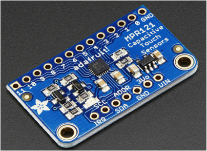
MPR121 breakout from Adafruit
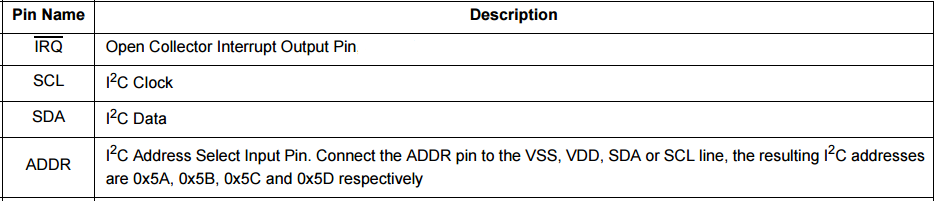
Note the pin configuration related to the ADDR pin. In case you have other I2C devices and their address conflicts with the default I2C address of MPR121 (0x5A), then address can be changed by connecting the ADDR pin to VSS, VDD, SDA or SCL line. The library i created gives the options to use any of the addresses while it defaults to 0x5A
Wiring
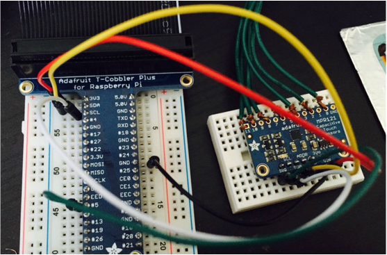
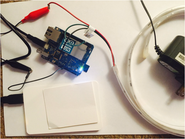
The hookup to Raspberry Pi is pretty straightforward. Apart from SCL/SDA and the Power/Ground hookups, only other hook up is the IRQ Pin to the GPIO Pin#5 on the Raspberry Pi 2. I am using an Adafruit Pi Cobbler but it can be hooked up directly to the PI. The Capacitive sensing pins are connected to some cardboard wrapped in aluminum foils.
The hookup to Raspberry Pi is pretty straightforward. Apart from SCL/SDA and the Power/Ground hookups, only other hook up is the IRQ Pin to the GPIO Pin#5 on the Raspberry Pi 2. I am using an Adafruit Pi Cobbler but it can be hooked up directly to the PI. The Capacitive sensing pins are connected to some cardboard wrapped in aluminum foils.
Interfacing
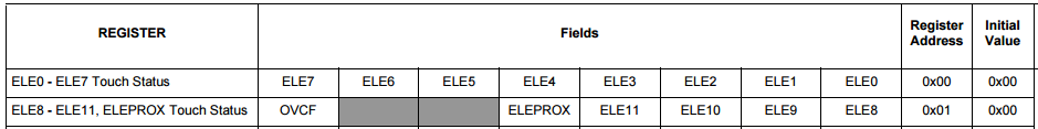
MPR121 board can be interfaced using I2C. Once I2C connection is established, specific registers can be read to get the status of the pins. The touch status for each pin is maintained as a bit. 1 to indicate touch and 0 to indicate no touch. By reading a byte at register 0x00, the touch status of the first 8 pins can be obtained. Five bits on the next register 0x01 indicate the status of the remaining 5 pins. Here is the register map:
MPR121 board can be interfaced using I2C. Once I2C connection is established, specific registers can be read to get the status of the pins. The touch status for each pin is maintained as a bit. 1 to indicate touch and 0 to indicate no touch. By reading a byte at register 0x00, the touch status of the first 8 pins can be obtained. Five bits on the next register 0x01 indicate the status of the remaining 5 pins. Here is the register map:
All the register information can be found in this datasheet. Also of interest would be all the application notes.
IRQ Pin
Brute force method is to read this register in a loop every few milliseconds to check if they are touched or not. Fortunately MPR121 provides an elegant way of notifying the status. Its has an IRQ pin that can be connected to any GPIO digital input pin on the micro controllers. The MPR121 pulls this pin Low when there is a status change on any of the capacitive pins. So instead of looping to detect change, the micro controller can read the Register only when the IRQ status changes. This library uses the IRQ pin for detecting cap sense change.
Driver Walkthrough
The code for this driver can be found at this Github repository.
1. Its a simple Universal Windows App class library. Since it needs to work with GPIO and I2C, added the Windows IoT Extensions for the UWP.
2. The library contains two constructors. The default one and the overloaded constructor to change the I2C address and the IRQ pin.
3. The I2C connection is established by calling the OpenConnection method. This method accepts a Windows IoT core device descriptor id sting of the I2C master on the Raspberry PI. Once connection is established, a soft reset command is issued. After setting up the capacitive sense threshholds as defined in the Application note, i hook up the Interrupt pin.
4. One of the great advantages of the Windows IoT core is the native event framework. It makes it quite easy to design the software to respond to events on the connected GPIO pins. So the GPIO pin is simply initialized and hooked up to the ValueChanged event. Whenever IRQ pin value changes, the GPIO pin 5 will raise the event and execute the attached event handler. Note that the event execution happens in a different thread than the UI thread.
5. Before we look at the ValueChanged event handler, a word on the PinId enum flag that i am using to identify the pins. If you notice the touch status register information above, one bit is used to indicate each pins status. So having them represented with flags Enum makes it natural to translate the data read from the registers. The Flags enum also has an HasFlags method that makes it quite easy to check which pins are touched/released.
6. When the value changed event handler is invoked, the MPR121 pulls the IRQ pin low. So i track for the FallingEdge on the GPIO pin. Also MPR121 expects the status registers to be read immediately. The status register will hold the data for that moment. If two pins are touched at the same time, the register will have the bits for both pins turned on. So by simply reading the two bytes from address 0x00 and casting it in to PinId enum, I get the list of pins that are currently touched. Additionally i want to expose both the touched and released events. So i compare it with the previous touched event and do necessary checks to obtain newly touched pins and newly released pins.
In order for the consumer hook up to simple Touched and Released events, i have included two events in the MPR121 class and invoke those two events with the appropriate event arguments.In addition i also update a Pins list the represents the continuous state of all the pins on the MPR121.
In order for the consumer hook up to simple Touched and Released events, i have included two events in the MPR121 class and invoke those two events with the appropriate event arguments.In addition i also update a Pins list the represents the continuous state of all the pins on the MPR121.
Sample Usage
The library is available in NuGet as well as Windows.IoT.Core.HWInterfaces.MPR121 . So it can be installed to your Universal Windows app targeting Raspberry Pi from Nuget using:
Install-Package Windows.IoT.Core.HWInterfaces.MPR121
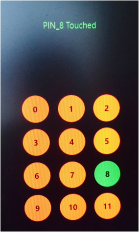
Once Installed, initialize the mpr121 , open connection and hook up the events. Here is simple UI the tracks the pins pressed and the associated code. The complete sample is available at the Github repository.
Future Considerations
The code might not be very tight. There is lot of room for refactoring. In addition, when time permits i hope to update this library to expose the GPIO configuration and the proximity sensing configuration. But all in all i ended up learning quite a few things when putting this together.
 RSS Feed
