I am sure this is something that most of us who have signed up for the Embedded Systems Shape the world course would be going through while waiting for the course to start on Jan 22. I have been anxious to get a first circuit built ever since I got the Tiva Launchpad for the edx course. Without writing any new code, and without frying the board i wanted to build some kind of circuit. So decided to use the launched QuickStart rgb application that came with the board as the base software and connect my external circuit to it.
Here is what we know about the pre-loaded RGB Quick Start application from the instruction leaflet that came pre-loaded with the Tiva Launchpad:
From the LaunchPad Evaluation Kit Manual I see the following pin mapping used by the RGB Quick start application
Here is what we know about the pre-loaded RGB Quick Start application from the instruction leaflet that came pre-loaded with the Tiva Launchpad:
- It controls the LED
- It uses the two buttons that are present on the board
From the LaunchPad Evaluation Kit Manual I see the following pin mapping used by the RGB Quick start application
| Table 2-2. User Switches and RGB LED Signals | ||
| GPIO Pin | Pin Function | USB Device |
| PF4 | GPIO | SW1 |
| PF0 | GPIO | SW2 |
| PF1 | GPIO | RGB LED (Red) |
| PF2 | GPIO | RGB LED (Blue) |
| PF3 | GPIO | RGD LED (Green) |
Circuit 1: Connecting External LEDs
If you have bought the full kit for the course, you should be having these parts already:
Here is the circuit: (its better you prepare the circuit before you plug in the USB)
If you have bought the full kit for the course, you should be having these parts already:
- 3 LEDS (colors don't matter)
- Jumper wires
- Breadboard
Here is the circuit: (its better you prepare the circuit before you plug in the USB)
- Connect a jumper wire from Gnd to the ground rail on breadboard ( Black wire in the picture)
- Plug in 3 LEDs to the breadboard with the shorter leg(cathode) to the ground rail and the longer leg (anode) in column "a" or "b" (color of the LED doesn't matter. But if you have bought the kit recommended for the course, you might have one of each color, Red, Green and Yellow.. ( I used 2 reds and an yellow.)
- Connect a jumper wire from PF1 to the column "d" or "e" in the same row where the Red Led's longer leg is plugged in (Red Wire in the picture)
- Connect a jumper wire from PF2 to the column "d" or "e" in the same row where the Green Led's longer leg is plugged in (Green Wire in the picture)
- Connect a jumper wire from PF3 to the column "d" or "e" in the same row where the Blue Led's longer leg is plugged in (Blue Wire in the picture)
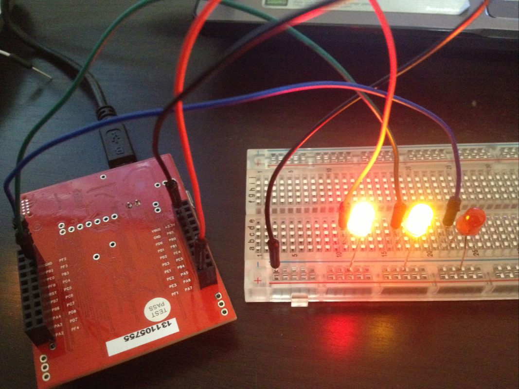
Make sure your circuit looks some what similar to the picture. The key part is to be careful about the jumper wires going to the Tiva. The LEDs won't blow out because they are, you guessed it, Diodes. Current flows in only one direction. And if my understanding of the board is correct, there are already resistors present on the board for the LED Pins.
If everything goes smooth, you can see that the intensity of the 3 LEDS change in sync with the LEDS that are already on the board.
If you press the buttons you will see the frequency change in the external LEDs also.
For me it was fun to see them working. I can't wait for the course to start to make use of all the features available in this board.
 RSS Feed
